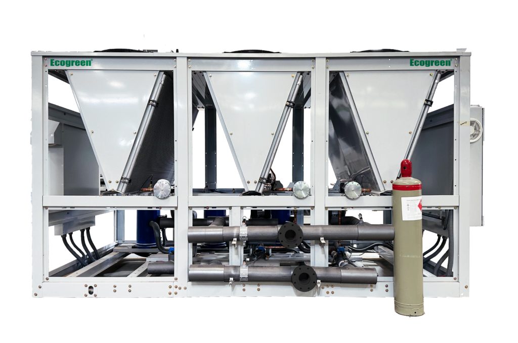
What is a Chiller?
liquid cooling units
Chillers
Liquid chillers or chilled water chillers are the ideal solution for your plastic and food processing and air conditioning requirements, ranging from 1.5 tons to over 2000 tons:
- Chiller Screw
- Chiller Scroll
- Piston or Semi-hermetic Chiller
- Centrifugal Chiller
- Chiller Absorption
These units have the advantage of delivering chilled water to remote processes by controlling the temperature of the molds or the process or to fan coil or air conditioning handling units at any distance by means of adequate pumping, a limitation that exists in the Mini and Multi Split, VRF systems.
Main parts or components:
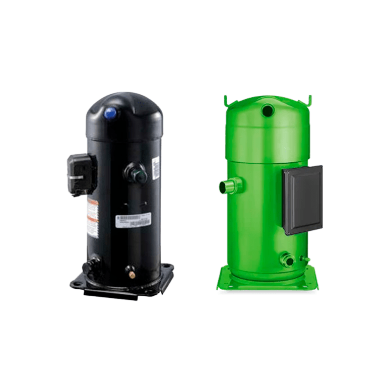
- Compressor
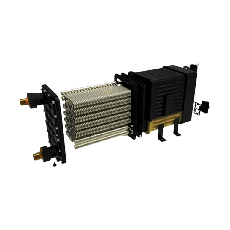
- Capacitor
- Expansion valve
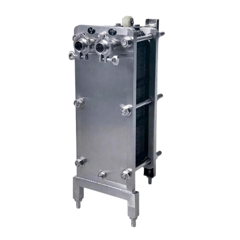
- Evaporator or exchanger
- Refrigerant gas (there are many types, the best known are R134, R410A, R404A, R507, R290 propane, in disuse R22.
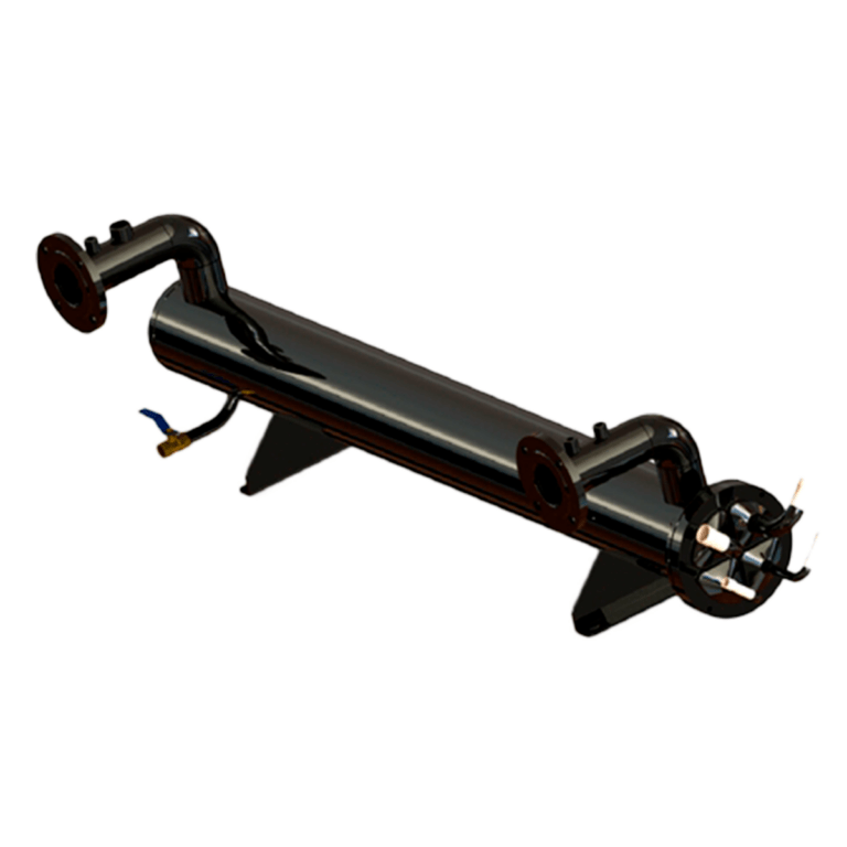
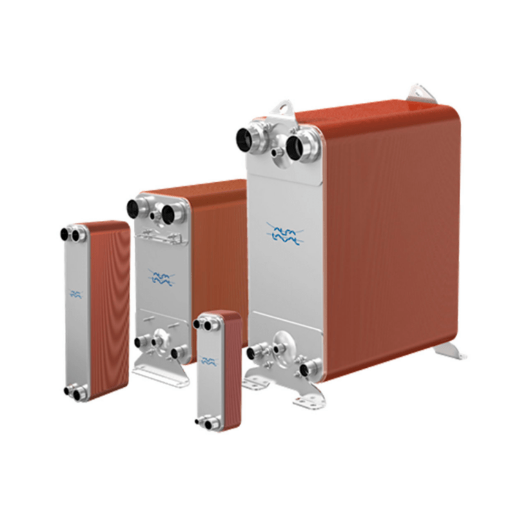
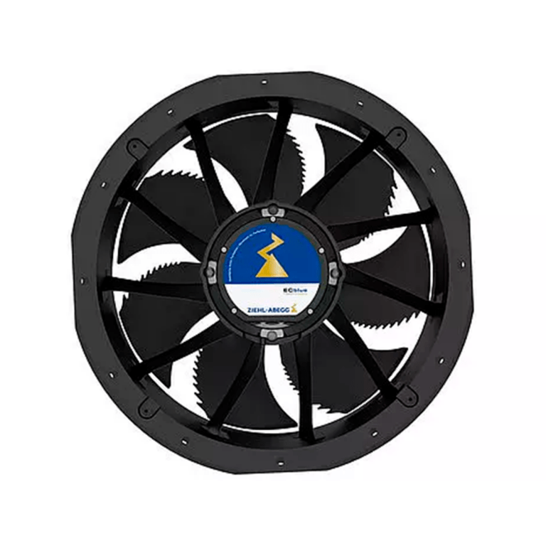
How does a chiller work to generate liquid cooling?
The compressor sucks the gas from the evaporator or heat exchanger (this is where the cooling effect is achieved by taking the heat from the cooled liquid) maintaining pressures in the exchanger from 0 to 120 psi pounds depending on the desired temperature of the water or liquid to be cooled.
It compresses the refrigerant gas to pressures of 150 to 550 psi or pounds depending on the refrigerant gas and ambient temperature or cooling water from a cooling tower which cools the condenser by discharging the gas into the condenser which is in turn cooled by air forced by a fan or by water from a cooling tower.
This is where the process heat is rejected to the atmosphere or water tower to maintain the discharge pressure of the compressor and remove the heat the refrigerant gas is condensed to this we call the refrigerant phase as a liquid.
This condensed gas in liquid form passes through the expansion valve which is nothing more than a restrictor orifice connected to the inlet of the evaporator or heat exchanger and creates an abrupt pressure drop from 450 psi pounds before the valve to 100 psi (R410A) after the expansion valve as it passes through the expansion valve or orifice the refrigerant carrying a high pressure of 450 psi (R410A refrigerant) drops to 75 or 100 psi or pounds.
This sudden change in pressure generates the evaporation of the refrigerant to go instantly from 450 psi to 75 psi which creates a cooling effect or cooling in the exchanger cooling its walls or tubes and where on the opposite side of the exchanger water flows. The water on contact with the surface of the heat exchanger is cooled to obtain chilled water at the desired temperature and the cooling cycle continues indefinitely through heat exchange. It maintains the process temperature by means of the cooling liquid cooled water or glycol.
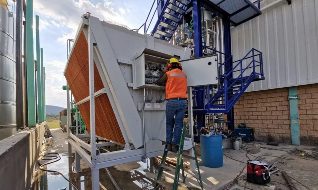
Chillers for Air Conditioning
What is an AMU Air Handling Unit or Fan Coil?
It is a coil of copper tubes finned in aluminum or similar to a radiator inside a box or sheet structure that contains a centrifugal fan and a motor that drives it. This fan draws air from the suction side of the air conditioning ducts and passes it through the coil. The coil is cooled by the chiller water to 7°C which recirculates from the chiller to the chilled water pumps to the piping. 12°C this cycle is continuous until the desired temperature point is reached in the cooled or conditioned space and controlled by a thermostat and a motor actuated valve that opens or closes interrupting the flow of chilled water to the coil depending on the signal sent by the thermostat.
This cannot be achieved with a cooling tower. Given the ambient temperatures only in very cold climates can there be this type of system the chiller if requested and designed can be heat pump type heating the system or process water for a cost up to 3 times lower compared to a boiler or boiler.
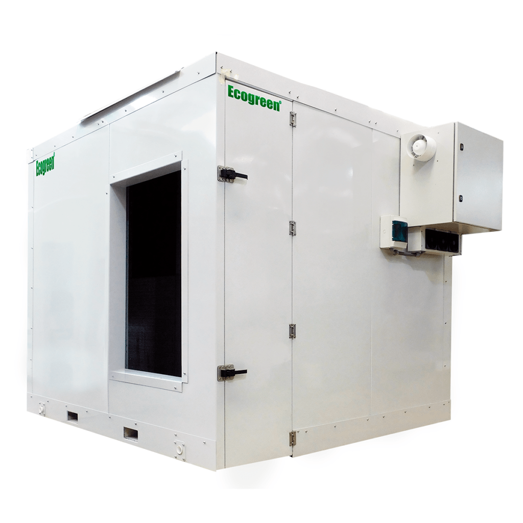
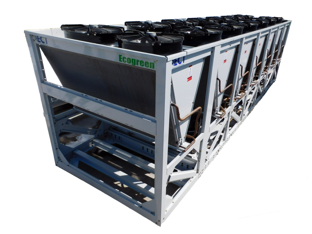
Heat Recovery
Reduces* the expense and maintenance of boilers with gas or carbon-based fuels. In addition to recovering heat from the compressor and preheating water to 50°C for:
- Boilers
- Boilers
- Services
- Showers
- Kitchens
- Swimming pools
- Handler reheat coils for humidity control
- Pasteurization
- Hot water free of charge*.
*Restrictions apply, ask factory.
Chiller Types
Air-Cooled Scroll Chillers
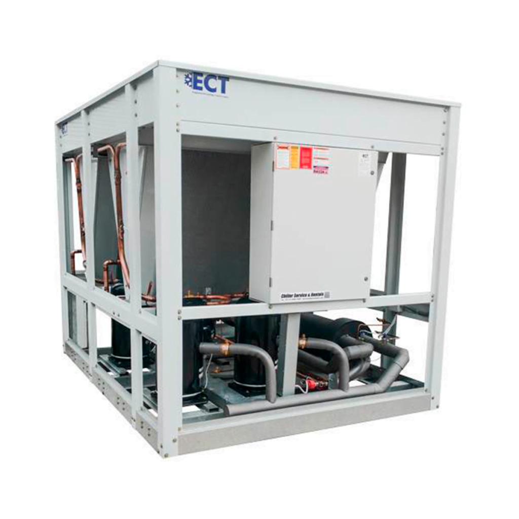
The air-cooled scroll chillers have a capacity range of 10 to 150 tr. They operate with HCFC-22, HFC 407C and HFC 410a using scroll compressors that provide high efficiency, low noise, unsurpassed liquid tolerance and high reliability.
These chillers are also controlled by the user-friendly Millennium Control Center with a Hydro Kit option that includes a water pump (1 or 2) and expansion tank contained within the unit.
Water-Cooled Scroll Chillers
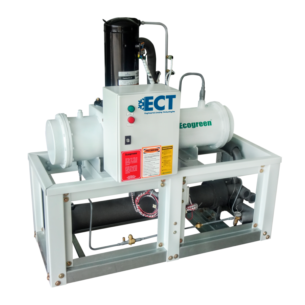
The water-cooled Scroll Chillers are high efficiency, low operating and installation costs, provide low noise level and excellent communication through its microprocessor control with 40-character display available.
With 5 languages for easy operation and maintenance, they are ideal for multiple applications as they are designed to operate in a wide range of conditions.
Air-cooled Screw Chillers
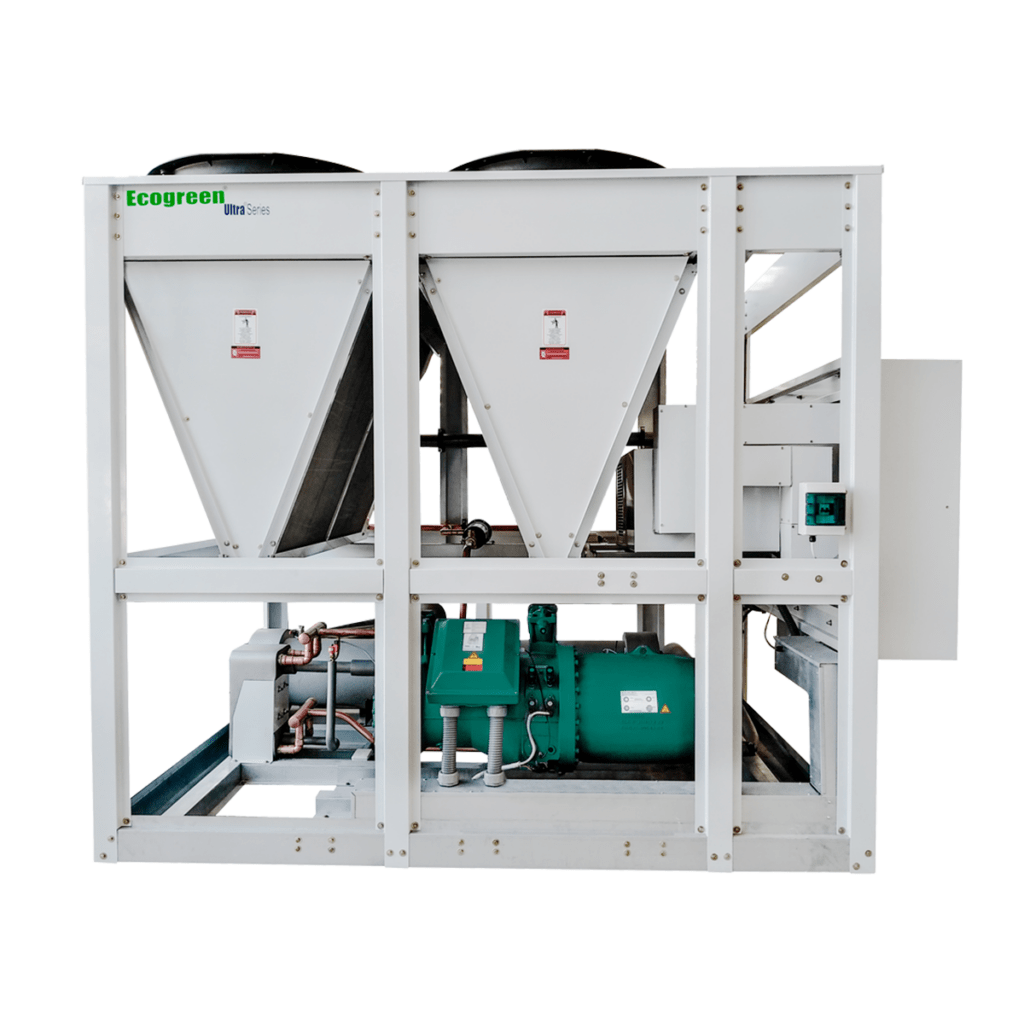
Air-cooled Screw Chillers provide high operational efficiency and a quiet level of operation, are available for capacities from 150 to 550 TR, providing 10.3 SEER efficiency at full load and 15.2 SEER at part load, use environmentally friendly HFC-134 refrigerant gas and 50% fewer moving parts than traditional compressors.
These units use variable speed drive technology to control the capacity of the compressors, allowing the best performance in the market for this type of equipment, ensuring a power factor of 0.95 at any capacity and avoiding energy peaks at compressor start-up that never exceed 100% of their FLA.
Water-Cooled Screw Chillers
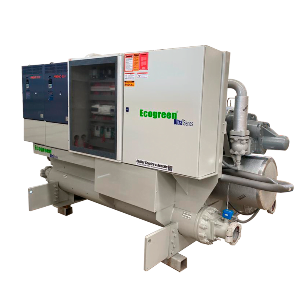
Water-cooled Screw Chillers provide the lowest sound levels known for screw chillers on the market. They have sound levels of only 79 DBA without any accessories and 68 DBA with sound covers, use HFC-134a refrigerant which has zero ozone depletion potential and are designed for long-term sustainability with minimal refrigerant loss.
Improvements to the unit's Frick compressors have reduced system losses, improving efficiency for maximum energy savings in the design. The chiller is designed with an advanced control panel that offers simple navigation in multiple languages and a built-in interface that communicates with most building automation systems.
Centrifugal Water-Cooled Chillers
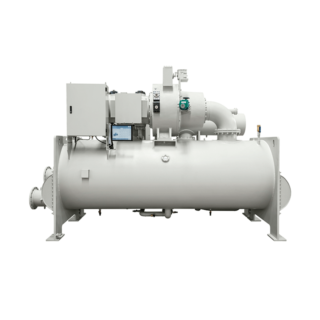
The centrifugal chillers operate with maximum efficiency for both full and partial loads, considering that 99% of the time the equipment works at partial loads, thus optimizing electrical energy consumption.
These chillers have the most advanced control panel in the market, achieving a totally user-friendly operation, registration and monitoring.
Water-Cooled Absorption Chillers
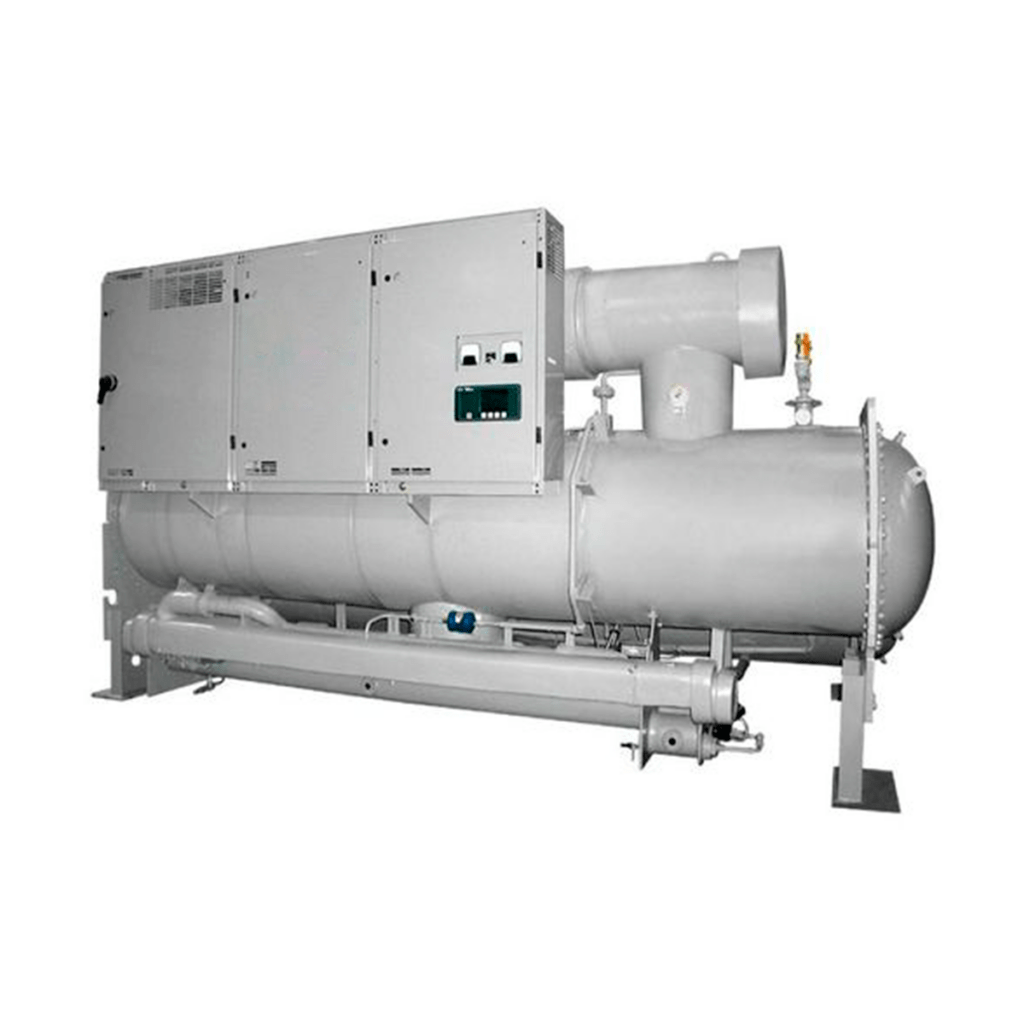
Water-cooled (single stage) absorption chillers use water as an environmentally friendly refrigerant and provide an economical source of cooling when low pressure steam or hot water can be used.
Their capacities range from 100 to 1,400 tr. If a residual steam discharge or hot water system from an engine cooling system or co-generative process is available, it can be used by a single-stage Millennium absorption water chiller for free cooling.
Chiller Selection Table
| HOW TO SELECT A CHILLER | |||||||
|---|---|---|---|---|---|---|---|
| 1.- | KNOWING THE FLOW RATE OF WATER OR LIQUID TO BE COOLED | ||||||
| Enter FLOW in liters per minute: | 59 | 15.61 | Gallons per minute | THERMAL REQUIREMENTS FOR ADVANCE DEL PACIFICO PIPELINES | |||
| Liters of water are converted to kilograms per hour. | |||||||
| FLOW | 59.00 | Lpm | FLOW | 16,000 LTS/H | |||
| 3,540.00 | Liters per hour | WITHOUT COOLING TOWER | |||||
| Liters of water = | 3,540.00 | Approximate kilograms | TEMP. INPUT | 35°C | |||
| Thermal Load | TEMP. OUTPUT | 6°C | |||||
| Liters/Kilograms per hour: | 3,540.00 | 186TR | |||||
| T1 | Enter inlet temperature: | 12.00 | °C | ||||
| T2 | Enter Output temperature: | 3.00 | °C | FLOW | 16,000 LTS/H | ||
| DT | Temperature differential: | 9.00 | °C | WITH COOLING TOWER | |||
| CP | enter the specific heat of the product: | 1.00 | TEMP. INPUT | 16°C | WINTER TEMPERATURE | ||
| Qt | Thermal Load per Hour | TEMP. OUTPUT | 6°C | ||||
| Qt = Product weight x DT (temperature differential) x cp considering 3024 calories per ton of refrigeration. | 52.9TR | ||||||
| Qt= FLOW lts. X | 9.00 X 1 cp | ||||||
| 3024 cal | FLOW | 16,000 LTS/H | |||||
| Qt= | 10.54 | tr of the process | IDEAL FOR ALL YEAR ROUND | ||||
| 1 ton = 3024 kilo calories or frigories | 31,860.00 | Kilo calories | TEMP. INPUT | 25°C | |||
| 1 ton = 12,000 btu | 126,428.57 | BTU | TEMP. OUTPUT | 6°C | |||
| 1 ton = 3,517 kw | 37.05 | Calorific kilowatts | 100.53TR | ||||
| 1 kilowatt hour (kW.h) = 860 kilocalories (kcal) | |||||||
